I’m going to continue this series while it’s still fresh in my mind. In case you missed it, part 1 is here.
I learned electronics when I was in High School. I had two years of electronics classes and I also built circuits out of digital logic gates as a hobby. This is in the late 70’s when Radio Shack sold chips in packages on the rack. One of the problems with the subject of electronics is that most of the knowledge you need to become an “expert” is very dry. To compound the problem, the subject is always taught with the basics of DC circuits and then the subject works up to AC circuits. All rather dry stuff until you arrive at the transistor. Then the subject of oscillators and amplifiers will put one to sleep just as fast (unless you’re interested that subject). If you know nothing about electronics you should still be able to buy the parts I listed in my last blog post and assemble the circuits I described without too much trouble.
In my last blog post I also assumed you have some small hand tools. If you purchased everything on the list provided, you might be wondering how to strip the ends of the wire or cut the wire to length. That would require a pair of diagonal cutters and maybe a pair of wire strippers. You might also need a pair of needle nose pliers to hold short wires. You can use scissors to cut 22 gauge wire, but your scissors might not be good for paper after that. The only tool you really need is this wire cutter/stripper:

You can find them at Jameco and they are cheaper here.
Larger Circuits
If you built the circuits in the previous blog post, you’ll realize that each circuit only involved one gate. Larger circuits can be built by connecting outputs of one gate to inputs of other gates. If you bought all the chips on the list that I provided, you should have 12 Inverters and an assortment of 40 other gates. You can create quite a large circuit with that many chips.
There are several problems you’ll run into if you keep building larger and larger circuits. First, you’ll probably run out of breadboard space. That’s easy to fix, just buy a bigger breadboard or a second board. But that’s not what I’m getting at here. Circuits have limitations as well. You should be aware of the limitations that you might run into and how to solve them.
One limitation is your power supply. If you wire up enough LEDs and chips, you can exceed the total amperage of your power supply. When that occurs, then your power supply will not be able to maintain the voltage that you have set and it might trip the built-in power protection. If this happens, you’ll need to get a larger power supply to run your circuit.
If your circuit is complicated and you connect a lot of gates together, you could run into the fan-out limitation. Each output can only drive so much current. This rating is listed in the spec sheet and you need to compute the current rating of each input your connected to in order to see if the output can handle it. This should only be looked at if you are connecting to more than about maybe 6 or 8 gates, or if you measure the output of your gate and it can’t achieve the voltage necessary to trigger a high (or maybe a low). You’ll need a meter to measure the voltage. This will probably be your first test tool. Don’t splurge for the expensive meter, just buy something like this:

Jameco sells this meter for $6.95. Click here. You can also shop around, Amazon might have an even better price.
Eventually, you’ll get into clocking circuits. You can build some pretty fast circuits that can do sequences, computations and other crazy stuff. When you get to this level of sophistication you’ll need to understand the basics of DC and AC circuits. Why? Because the real-world is not perfect. A signal traveling down a wire and through a circuit takes physical time. It’s lightning fast, but the delay is still there. Voltages will not switch exactly between 0 volts and 5 volts. There is a transition time and there are overshoots (when the signal spikes beyond the top of the square wave). This overshoot looks like this:

As you increase the speed of your circuit, this imperfection becomes a real problem.
Circuit switching can cause spikes to form on your power. This can transmit to adjacent chips and cause errors in your circuit. There is a simple remedy for that and it involves installing a capacitor near the power lead of your chips. If you own an oscilloscope, you can put your probe on the power supply and see the spikes. Here’s a photo that shows how capacitors (orange and yellow) are installed near memory chips on an old circuit board:

None of these “problems” are difficult to overcome. You just need to be aware that they exist. Oh, and there are so many more complicated issues that can occur. Don’t let that scare you away from enjoying this hobby/career.
The Binary System
The binary system only has two symbols a zero and a one. So numbers in binary take more digits than the decimal system that people are most familiar with. Here’s an example of a 3-digit binary number counting from zero to 7 (binary is on the left and decimal is on the right):

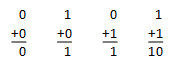
When we add two numbers together in binary, it’s similar to decimal. If both inputs are zero, then the output is zero. If either input is a one, then the output is a one. If both inputs are one, then we need to set the output to zero and carry the one. This is just like carrying a one when we add 9+1 in the decimal system:
Your Next Circuit
Let’s build a binary adder. We’re going to start out with the simplest circuit. The one-bit half adder. Here’s the circuit and truth table:

The first thing you’ll notice is the exclusive or gate. You can purchase a TTL XOR gate (74LS86) or you can build one out of NAND gates. Which is what we’re going to do. So change your circuit to this:

The NAND gate and the NOR gate have a special relationship to digital circuits. They are the universal gates. Any gate types can be built with just NAND gates (or just NOR gates). Here is a list of gates and their NAND gate substitution:

Now, if you run out of OR gates, you can build one out of any spare NAND gates.
Back to our fancy half-adder circuit. I’m going to add the pin numbers to the NAND gate chip so you can wire this easily:

Setup your breadboard and find a 74LS00 and a 74LS08. Plug these into your breadboard like this:

I added two LEDs with resistors (100 ohm) connecting the cathode to ground. This is the same as in previous circuits. You can pre-check your LED wiring by connecting the other side to positive and see if the LED lights up. If it does, then you’re good. If it doesn’t light up, then reverse the LED leads and try again. Also, make sure the markings on your chips face up (look for pin 1).
Wire the output of the sum (NAND gate pin 11) to the lower LED and wire the output of the carry (AND gate pin 3) to the upper LED:

If you have power applied, you’ll notice that the carry LED has lit up. That’s because there is nothing connected to the inputs of your AND gates and if you remember, TTL treats an unconnected input as a “1” or high. Now wire up the rest of your gates. I’ve taken photos of all 4 combinations of inputs, from left to right, 00, 01, 10, 11 (click to zoom):

Here’s another copy of the truth table to check your work:

Review
So what did we learn?
- The NAND and NOR gates are universal and can replace any other gate.
- The binary system only uses the numbers zero and one.
- Using a simple circuit we can add two one-bit numbers together.